Library Contents Search the Library RV Tech Library Help Page Site Map About Us Tiffin RV Network TRVN Classifieds Campground Reviews Photo Gallery TRVN Store
Appliances Batteries Boondocking/Dry Camping Chassis Clubs & Forums Electrical Electronics Engines Exterior Maintenance Generators Heating & Air Conditioning Interior Maintenance Misc Items Operating Tips Plumbing Red Bay Safety & Health Storage Supplier Contacts Tires and Wheel Rims Towing Transmissions Weighing
![]()
How to Adjust the Automatic Leveling
Sensor on the HWH 625 Series
Overview:
Levelers come in a wide variety of designs. Generally mechanical systems are designed by Atwood while the hydraulic systems are built by HWH Corporation. There have been a number of different designs and variations over the years but this topic will deal with the adjustment of the auto-leveling sensor on the popular HWH 625 series, which is a recent design that is very popular. It's the same setup as used on both my 2004 Allegro Bus and my 2007 Bus.
Automatic leveling systems are supposed to automatically lower the jacks and level the RV with the push of a button. The system uses microprocessors to lower the appropriate jacks and raise the coach to a level condition. Of course, in order to do this it needs to know when the coach is level. Therefore a sensor is incorporated into the design to tell the microprocessors which jacks to lower and when to stop. Normally this works pretty good but occasionally the sensor gets out of whack from the normal vibration caused by bouncing down the road. In that case it needs to be readjusted. While some of the earlier systems used a pendulum design that triggered the various switches in the system, the 625 series is more high tech and uses microprocessors and software algorithms to perform this function. It also handles automatic dumping and filling of the air bags whenever the jacks are put into the "Auto Level" mode or "Store" mode. The following section will detail how the automatic leveling sensor works and how to adjust it.
How It Works:
Following is a picture of the HWH 625 leveling system control module.
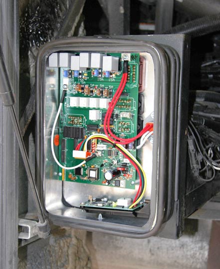
The 625 series controller is mounted on the face of the hydraulic pump and motor assembly. My son says it looks like the flux capacitor from the Delorean in the Back to the Future movie. On my coach it's located right next to the batteries. If you can't find yours, just press the auto-level button and track down where all the pump motor noise is coming from. The control circuitry is located behind a clear plexiglas panel that is held in place by a rubber grommet. For illustration purposes I removed this panel to eliminate glare when photographing the various components. You DO NOT have to remove this panel to adjust the sensor. I highly recommend not removing the panel because it is a real pain to stuff it into the grommet when you reassemble it.
The master board contains a number of relays and fuses that control the various operations. You really don't need to mess with this board unless you have blow fuses or faulty relays. If that's the case you should be looking at the service manual, which is also found in this library. In the above image you'll notice in the bottom of the case there is a smaller circuit board. This is the auto-leveling board that you'll be dealing with.
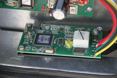
In the above two images you can see close-ups of the board as well as the hex nut and screw that mounts this board to the lower right side of the control box. The PCB is mounted to a plastic framework with pivot points and spring tension. This framework is attached to the housing via the hex nut and screw. This nut and screw are also the adjusting points for the leveling board so those are the items you'll be dealing with.
Step 1 is to manually level the coach. Use the control pad to manually level the coach to your satisfaction. Use a small spirit level to establish what "level" is. Normally there are a few variations within a coach so "level" in one spot may not be "level" in another. Some RVers like to lay the level on the floor, some like to lay it on a counter top, and my personal choice is to set it vertically in the bathroom door jam so that the door doesn't swing open or closed by itself once the coach is level. It really isn't all that important because today's refrigerators aren't as picky as they used to be so they do have quite a bit of tolerance.
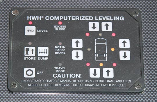
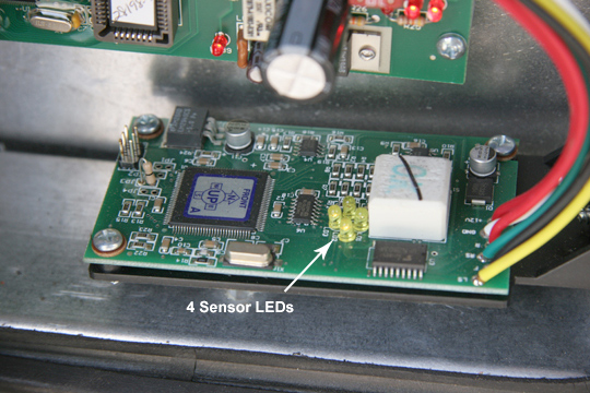
Once you have the coach leveled to your satisfaction. Look at the above control panel and you will see that certain amber LEDs are lit. These LEDs indicate which side of the coach the system "thinks" is low. Once the sensor is properly calibrated, all 4 of these LEDs will no longer be illuminated. Note in the following close-up image that there are 4 Sensor LEDs located on the board itself. These LEDS will report the same information as the ones on your remote control panel so you don't have to run back and forth between the driver's area and the HWH system when performing these adjustments.
In order to calibrate these LEDs so that none are lit once the coach is level the board needs to be adjusted. The adjustment of this board is accomplished by twisting the hex nut and adjusting the screw head on the mounting bracket.
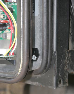
This bracket is better illustrated in the above image. The large black hex will adjust the left-to-right settings while the phillips/hex head screw is used to adjust the front-to-rear setting. Once these are properly adjusted, none of the 4 LEDs will be lit on the PCB and none of the 4 amber LEDs will be lit on the remote control panel inside the coach. Your coach will then auto-level properly.
So, Step 2 is to adjust the board. I prefer to adjust the side-to-side setting via the hex nut first. Once I have it set, I continue to hold the 1" box end wrench on the nut so that it doesn't move while I adjust the screw that controls the forward-aft settings. Turn the hex real far in one direction and you'll see one LED light. Then turn it the other way and you'll see that LED go out and the other one light up. Now that you know which is which, adjust the hex so that they both go out. The small circuit board should look pretty level at that point. Next, while continuing to hold the hex nut to prevent it from moving, adjust the screw in the same manner to set the front-to-rear settings. Once all 4 LEDs are no longer illuminated you should be all set. You may have to go back and forth a few times to fine tune it to that position. It doesn't take very much. Just a slight nudge will accomplish alot so don't get too ham handed. Pretend that you're James Bond de-arming a nuclear warhead.
Step 3 is to test it. Go into the coach and totally store the jacks. Then switch the ignition key to the OFF position and back ON again to reset the system. Press the Auto-Level button twice to begin the process and wait to see the results. The coach should relevel itself and all 4 LEDs should be out, both on the remote control panel, and on the printed circuit board. If the coach still is not level, check it again with your hand level. It's possible that it wasn't really level when you first calibrated it. If so, repeat the procedure and try it again.
Note that there is a second screw hole directly above the phillips/hex head adjusting screw. This is used to adjust the spring tension and is also the pivot point. You should not adjust this screw unless the spring has come loose or you need to replace the PCB. There should be a small dob of silicone over that screw hole to prevent water penetration into the housing. If the silicone is gone, be sure to stick another dob over that hole.
Submitted by Mark Quasius - 2/07/06
Click Your browser's "Back" button to return to the previous page
or chose another category from the side menu.
The RV Tech Library is brought to you by the TiffinRVnetwork
Absolutely No Affiliation exists between this group and Tiffin Motor Homes Inc or the Allegro Club. This website neither endorses or discourages the use or purchase of a Tiffin product. All references, suggestions, comments, etc. contained herein are the opinions/experiences of the posters and not those of Tiffin Motor Homes Inc. or the website administrators.
|
|